17.8 Настройка ERPS
17.8.1 Обзор
Введение в функциональность
Технология ERPS увеличивает доступность и надежность Ethernet-колец. В случае обрыва оптических волокон ERPS обеспечивает время сходимости менее одной секунды, часто менее 50 миллисекунд.
Основная идея описана следующим образом. ERPS работает, создавая домен ERPS в одном кольце. В этом кольцевом домене один коммутатор или узел назначается главным узлом (master), а все остальные узлы назначаются транзитными (transit). Один порт главного узла назначается основным портом кольца, а другой порт назначается вторичным портом. В нормальном режиме главный узел блокирует вторичный порт для всего трафика, не относящегося к ERPS-домену, тем самым предотвращая появление петли в кольце. Главный узел отправляет keep-alive сообщения с заданным интервалом. Транзитные узлы в кольцевом домене пересылают эти сообщения. Когда возникает событие отказа соединения, главный узел определяет это либо получив сообщение об отказе соединения от узла, находящегося рядом с отказавшим соединением, либо при истечении тайм-аута keep-alive сообщения. После обнаружения отказа соединения главный узел открывает вторичный порт для перенаправления трафика.
Описание принципа
Ссылка: RFC 3619
17.8.2 Конфигурация
ERPS — протокол с мягкими состояниями. Основное требование это включить ERPS на нужных устройствах и правильно настроить информацию ERPS для различных топологий сети.
Этот раздел предоставляет примеры конфигурации ERPS для типичных топологий сети.
Настройка ERPS для топологии с одним кольцом (Single-Ring Topology)
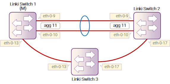
Рисунок 17-15: ERPS
На Switch1, Switch2 и Switch3 настроен один и тот же домен ERPS и кольцо. Switch1 настроен как главный узел ERPS, а два других коммутатора настроены как транзитные узлы ERPS. Интерфейс agg11, который включает два участника: eth-0-9 и eth-0-10, настроен как основной интерфейс на Switch1, а eth-0-13 настроен как вторичный интерфейс.
Порты, подключенные к кольцу ERPS, должны быть настроены как транковые порты, позволяя проходить трафику VLAN данных. Если включена стековая конфигурация, порт кольца ERPS не должен находиться на подчиненном устройстве стека.
- Порты, подключенные к кольцу ERPS, должны быть членами контрольного VLAN, чтобы пакеты ERPS могли отправляться и приниматься.
- STP на портах, подключенных к кольцу ERPS, должен быть отключен.
- Только один узел может быть настроен как главный.
- Контрольный VLAN не должен быть настроен как интерфейс третьего уровня.
- На портах ERPS не должно быть включено VLAN mapping.
- Native VLAN порта, подключающегося к кольцу ERPS, не должна быть установлена в качестве основной control VLAN или вторичной control VLAN.
Следующая конфигурация должна быть применена ко всем коммутаторам, если идентификатор коммутатора не указан.
Шаг 1: Вход в режим конфигурации
Switch# configure terminal
Шаг 2: Вход в режим конфигурации VLAN и создание VLAN
Switch(config)# vlan database
Switch(config-vlan)# vlan 15
Switch(config-vlan)# exit
Шаг 3: Настройка параметров интерфейса
Как показано на топологии, порты eth-0-9 и eth-0-10 коммутаторов Switch1 и Switch2 подключаются к agg11 и соединяются напрямую. Порт eth-0-13 коммутатора Switch1 и порт eth-0-13 коммутатора Switch3 соединяются напрямую. Порт eth-0-17 коммутатора Switch2 и порт eth-0-17 коммутатора Switch3 соединяются напрямую.
Интерфейс agg11 для Switch1 и Switch2:
Switch(config)# interface eth-0-9
Switch(config-if)# no shutdown
Switch(config-if)# switchport mode trunk
Switch(config-if)# switchport trunk allowed vlan add 15
Switch(config-if)# static-channel-group 11
Switch(config-if)# exit

Switch(config)# interface eth-0-10
Switch(config-if)# no shutdown
Switch(config-if)# switchport mode trunk
Switch(config-if)# switchport trunk allowed vlan add 15
Switch(config-if)# static-channel-group 11
Switch(config-if)# exit

Switch(config)# interface agg11
Switch(config-if)# spanning-tree port disable
Интерфейс eth-0-13 для Switch1 и Switch3:
Switch(config)# interface eth-0-13
Switch(config-if)# no shutdown
Switch(config-if)# switchport mode trunk
Switch(config-if)# switchport trunk allowed vlan add 15
Switch(config-if)# spanning-tree port disable
Switch(config-if)# exit
Интерфейс eth-0-17 для Switch2 и Switch3:
Switch(config)# interface eth-0-17
Switch(config-if)# no shutdown
Switch(config-if)# switchport mode trunk
Switch(config-if)# switchport trunk allowed vlan add 15
Switch(config-if)# spanning-tree port disable
Switch(config-if)# exit
Шаг 4: Создание и включение домена ERPS
ERPS-домен для Switch1:
Switch(config)# erps 11
Switch(config)# erps 11 primary control vlan 15
Switch(config)# erps 11 mstp instance 0
Switch(config)# erps 11 ring 1 level primary
Switch(config)# erps 11 ring 1 mode master
Switch(config)# erps 11 ring 1 primary interface agg11
Switch(config)# erps 11 ring 1 secondary interface eth-0-13
Switch(config)# erps 11 ring 1 enable
Switch(config)# erps 11 enable
ERPS-домен для Switch2:
Switch(config)# erps 11
Switch(config)# erps 11 primary control vlan 15
Switch(config)# erps 11 mstp instance 0
Switch(config)# erps 11 ring 1 level primary
Switch(config)# erps 11 ring 1 mode transit
Switch(config)# erps 11 ring 1 primary interface agg11
Switch(config)# erps 11 ring 1 secondary interface eth-0-17
Switch(config)# erps 11 ring 1 enable
Switch(config)# erps 11 enable
ERPS-домен для Switch3:
Switch(config)# erps 11
Switch(config)# erps 11 primary control vlan 15
Switch(config)# erps 11 mstp instance 0
Switch(config)# erps 11 ring 1 level primary
Switch(config)# erps 11 ring 1 mode transit
Switch(config)# erps 11 ring 1 primary interface eth-0-17
Switch(config)# erps 11 ring 1 secondary interface eth-0-13
Switch(config)# erps 11 ring 1 enable
Switch(config)# erps 11 enable
Шаг 5: Выход из режима конфигурации
Switch(config)# end
Шаг 6: Проверка
Отображение результата на Switch1:
Switch# show erps 11
ERPS domain ID: 11
ERPS domain name: ERPS0011
ERPS domain mode: normal
ERPS domain primary control VLAN ID: 15
ERPS domain sub control VLAN ID: 0
ERPS domain hello timer interval: 1 second(s)
ERPS domain fail timer interval: 3 second(s)
ERPS domain protected mstp instance: 0
ERPS ring ID: 1
ERPS ring level: primary
ERPS ring 1 node mode: master
ERPS ring 1 node state: complete
ERPS ring 1 primary interface name: agg11          state:unblock
ERPS ring 1 secondary interface name: eth-0-13     state:block
ERPS ring 1 stats:
Sent:
  total packets:51
  hello packets:47                    ring-up-flush-fdb packets:2
  ring-down-flush-fdb packets:2       link-down packets:0
  edge-hello packets:0                major-fault packets:0
Received:
  total packets:21
  hello packets:21                    ring-up-flush-fdb packets:0
  ring-down-flush-fdb packets:0       link-down packets:0
  edge-hello packets:0                major-fault packets:0
Отображение результата на Switch2:
Switch# show erps 11
ERPS domain ID: 11
ERPS domain name: ERPS0011
ERPS domain mode: normal
ERPS domain primary control VLAN ID: 15
ERPS domain sub control VLAN ID: 0
ERPS domain hello timer interval: 1 second(s)
ERPS domain fail timer interval: 3 second(s)
ERPS domain protected mstp instance: 0
ERPS ring ID: 1
ERPS ring level: primary
ERPS ring 1 node mode: transit
ERPS ring 1 node state: link up
ERPS ring 1 primary interface name: agg11          state:unblock
ERPS ring 1 secondary interface name: eth-0-17     state:unblock
ERPS ring 1 stats:
Sent:
  total packets:0
  hello packets:0                     ring-up-flush-fdb packets:0
  ring-down-flush-fdb packets:0       link-down packets:0
  edge-hello packets:0                major-fault packets:0
Received:
  total packets:114
  hello packets:113                   ring-up-flush-fdb packets:1
  ring-down-flush-fdb packets:0       link-down packets:0
  edge-hello packets:0                major-fault packets:0
Отображение результата на Switch3:
Switch# show erps 11
ERPS domain ID: 11
ERPS domain name: ERPS0011
ERPS domain mode: normal
ERPS domain primary control VLAN ID: 15
ERPS domain sub control VLAN ID: 0
ERPS domain hello timer interval: 1 second(s)
ERPS domain fail timer interval: 3 second(s)
ERPS domain protected mstp instance: 0
ERPS ring ID: 1
ERPS ring level: primary
ERPS ring 1 node mode: transit
ERPS ring 1 node state: link up
ERPS ring 1 primary interface name: eth-0-17       state:unblock
ERPS ring 1 secondary interface name: eth-0-13     state:unblock
ERPS ring 1 stats:
Sent:
  total packets:0
  hello packets:0                     ring-up-flush-fdb packets:0
  ring-down-flush-fdb packets:0       link-down packets:0
  edge-hello packets:0                major-fault packets:0
Received:
  total packets:130
  hello packets:129                   ring-up-flush-fdb packets:1
  ring-down-flush-fdb packets:0       link-down packets:0
  edge-hello packets:0                major-fault packets:0
Конфигурация топологии с пересекающимися кольцами (Intersecting-Ring Topology)
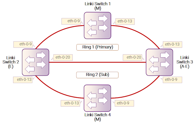
Рисунок 17-16: ERPS
Настройте одинаковую доменную область ERPS на коммутаторах Switch1, Switch2, Switch3 и Switch4. Коммутаторы Switch1, Switch2 и Switch3 составляют основное кольцо ERPS 1, а коммутаторы Switch2, Switch3 и Switch4 составляют подкольцо ERPS 2. Коммутатор Switch1 настроен как главный узел кольца ERPS 1, а два других коммутатора настроены как промежуточные узлы ERPS, в то время как коммутатор Switch4 настроен как главный узел кольца ERPS 2. Кроме того, коммутатор Switch2 настроен как граничный узел, а коммутатор Switch3 настроен как вспомогательный граничный узел.
Порты, подключающиеся к кольцу ERPS, должны быть настроены как транковые порты, разрешающие прохождение трафика данных VLAN.
Шаг 1: Вход в режим конфигурации
Switch# configure terminal
Шаг 2: Введите режим конфигурации VLAN и создайте VLAN
Switch(config)# vlan database
Switch(config-vlan)# vlan 11,12
Switch(config-vlan)# exit
Шаг 3: Введите режим конфигурации интерфейса и настройте атрибуты интерфейса
Switch(config)# interface eth-0-9
Switch(config-if)# no shutdown
Switch(config-if)# switchport mode trunk
Switch(config-if)# switchport trunk allowed vlan add 11,12
Switch(config-if)# spanning-tree port disable
Switch(config-if)# exit

Switch(config)# interface eth-0-13
Switch(config-if)# no shutdown
Switch(config-if)# switchport mode trunk
Switch(config-if)# switchport trunk allowed vlan add 11,12
Switch(config-if)# spanning-tree port disable
Switch(config-if)# exit
Настройка интерфейса eth-0-20 для коммутаторов Switch2 и Switch3:
Switch(config)# interface eth-0-20
Switch(config-if)# no shutdown
Switch(config-if)# switchport mode trunk
Switch(config-if)# switchport trunk allowed vlan add 11,12
Switch(config-if)# spanning-tree port disable
Switch(config-if)# exit
Шаг 4: Создайте и активируйте домен ERPS.
Домен ERPS для коммутатора Switch1:
Switch(config)# erps 1
Switch(config)# erps 1 primary control vlan 11
Switch(config)# erps 1 sub control vlan 12
Switch(config)# erps 1 mstp instance 0
Switch(config)# erps 1 ring 1 level primary
Switch(config)# erps 1 ring 1 mode master
Switch(config)# erps 1 ring 1 primary interface eth-0-9
Switch(config)# erps 1 ring 1 secondary interface eth-0-13
Switch(config)# erps 1 ring 1 enable
Switch(config)# erps 1 enable
Домен ERPS для коммутатора Switch2:
Switch(config)# erps 1
Switch(config)# erps 1 primary control vlan 11
Switch(config)# erps 1 sub control vlan 12
Switch(config)# erps 1 mstp instance 0
Switch(config)# erps 1 ring 1 level primary
Switch(config)# erps 1 ring 1 mode transit
Switch(config)# erps 1 ring 1 primary interface eth-0-9
Switch(config)# erps 1 ring 1 secondary interface eth-0-20
Switch(config)# erps 1 ring 1 enable

Switch(config)# erps 1 ring 2 level sub
Switch(config)# erps 1 ring 2 edge-mode edge
Switch(config)# erps 1 ring 2 edge interface eth-0-13
Switch(config)# erps 1 ring 2 common interface eth-0-20
Switch(config)# erps 1 ring 2 srpt disable
Switch(config)# erps 1 ring 2 enable
Switch(config)# erps 1 enable
Домен ERPS для коммутатора Switch3:
Switch(config)# erps 1
Switch(config)# erps 1 primary control vlan 11
Switch(config)# erps 1 sub control vlan 12
Switch(config)# erps 1 mstp instance 0
Switch(config)# erps 1 ring 1 level primary
Switch(config)# erps 1 ring 1 mode transit
Switch(config)# erps 1 ring 1 primary interface eth-0-13
Switch(config)# erps 1 ring 1 secondary interface eth-0-20
Switch(config)# erps 1 ring 1 enable

Switch(config)# erps 1 ring 2 level sub
Switch(config)# erps 1 ring 2 edge-mode assistant-edge
Switch(config)# erps 1 ring 2 edge interface eth-0-9
Switch(config)# erps 1 ring 2 common interface eth-0-20
Switch(config)# erps 1 ring 2 enable
Switch(config)# erps 1 enable
Домен ERPS для коммутатора Switch4:
Switch(config)# erps 1
Switch(config)# erps 1 sub control vlan 12
Switch(config)# erps 1 mstp instance 0
Switch(config)# erps 1 ring 2 level sub
Switch(config)# erps 1 ring 2 mode master
Switch(config)# erps 1 ring 2 primary interface eth-0-9
Switch(config)# erps 1 ring 2 secondary interface eth-0-13
Switch(config)# erps 1 ring 2 enable
Switch(config)# erps 1 enable
Шаг 5: Выйдите из режима конфигурации
Switch(config)# end
Шаг 6: Проверка
Отобразите результат на коммутаторе Switch1.
Switch# show erps 1
ERPS domain ID: 1
ERPS domain name: ERPS001
ERPS domain mode: normal
ERPS domain primary control VLAN ID: 11
ERPS domain sub control VLAN ID: 12
ERPS domain hello timer interval: 1 second(s)
ERPS domain fail timer interval: 3 second(s)
ERPS domain protected mstp instance: 0
ERPS ring ID: 1
ERPS ring level: primary
ERPS ring 1 node mode: master
ERPS ring 1 node state: complete
ERPS ring 1 primary interface name: eth-0-9        state:unblock
ERPS ring 1 secondary interface name: eth-0-13     state:block
ERPS ring 1 stats:
Sent:
  total packets:1310
  hello packets:1303                  ring-up-flush-fdb packets:3
  ring-down-flush-fdb packets:4       link-down packets:0
  edge-hello packets:0                major-fault packets:0
Received:
  total packets:921
  hello packets:921                   ring-up-flush-fdb packets:0
  ring-down-flush-fdb packets:0       link-down packets:0
  edge-hello packets:0                major-fault packets:0
Отобразите результат на коммутаторе Switch2.
Switch# show erps 1
ERPS domain ID: 1
ERPS domain name: ERPS001
ERPS domain mode: normal
ERPS domain primary control VLAN ID: 11
ERPS domain sub control VLAN ID: 12
ERPS domain hello timer interval: 1 second(s)
ERPS domain fail timer interval: 3 second(s)
ERPS domain protected mstp instance: 0
ERPS ring ID: 1
ERPS ring level: primary
ERPS ring 1 node mode: transit
ERPS ring 1 node state: link up
ERPS ring 1 primary interface name: eth-0-9        state:unblock
ERPS ring 1 secondary interface name: eth-0-20     state:unblock
ERPS ring 1 stats:
Sent:
  total packets:0
  hello packets:0                     ring-up-flush-fdb packets:0
  ring-down-flush-fdb packets:0       link-down packets:0
  edge-hello packets:0                major-fault packets:0
Received:
  total packets:988
  hello packets:985                   ring-up-flush-fdb packets:2
  ring-down-flush-fdb packets:1       link-down packets:0
  edge-hello packets:0                major-fault packets:0
ERPS ring ID: 2
ERPS ring level: sub
ERPS ring 2 node mode: transit
ERPS ring 2 edge node mode: edge
ERPS ring 2 node state: link up
ERPS ring 2 edge interface name: eth-0-13       state: unblock
ERPS ring 2 common interface name: eth-0-20     state: unblock
EPRS ring 2 SRPT is disabled
ERPS ring 2 stats:
Sent:
  total packets:0
  hello packets:0                     ring-up-flush-fdb packets:0
  ring-down-flush-fdb packets:0       link-down packets:0
  edge-hello packets:0                major-fault packets:0
Received:
  total packets:858
  hello packets:856                   ring-up-flush-fdb packets:1
  ring-down-flush-fdb packets:1       link-down packets:0
  edge-hello packets:0                major-fault packets:0
Отобразите результат на коммутаторе Switch3.
Switch# show erps 1
ERPS domain ID: 1
ERPS domain name: ERPS001
ERPS domain mode: normal
ERPS domain primary control VLAN ID: 11
ERPS domain sub control VLAN ID: 12
ERPS domain hello timer interval: 1 second(s)
ERPS domain fail timer interval: 3 second(s)
ERPS domain protected mstp instance: 0
ERPS ring ID: 1
ERPS ring level: primary
ERPS ring 1 node mode: transit
ERPS ring 1 node state: link up
ERPS ring 1 primary interface name: eth-0-13       state:unblock
ERPS ring 1 secondary interface name: eth-0-20     state:unblock
ERPS ring 1 stats:
Sent:
  total packets:0
  hello packets:0                     ring-up-flush-fdb packets:0
  ring-down-flush-fdb packets:0       link-down packets:0
  edge-hello packets:0                major-fault packets:0
Received:
  total packets:645
  hello packets:644                   ring-up-flush-fdb packets:1
  ring-down-flush-fdb packets:0       link-down packets:0
  edge-hello packets:0                major-fault packets:0
ERPS ring ID: 2
ERPS ring level: sub
ERPS ring 2 node mode: transit
ERPS ring 2 edge node mode: assistant edge
ERPS ring 2 node state: link up
ERPS ring 2 edge interface name: eth-0-9        state: unblock
ERPS ring 2 common interface name: eth-0-20     state: unblock
ERPS ring 2 stats:
Sent:
  total packets:0
  hello packets:0                     ring-up-flush-fdb packets:0
  ring-down-flush-fdb packets:0       link-down packets:0
  edge-hello packets:0                major-fault packets:0
Received:
  total packets:645
  hello packets:644                   ring-up-flush-fdb packets:1
  ring-down-flush-fdb packets:0       link-down packets:0
  edge-hello packets:0                major-fault packets:0
Отобразите результат на коммутаторе Switch4.
Switch# show erps 1
ERPS domain ID: 1
ERPS domain name: ERPS001
ERPS domain mode: normal
ERPS domain primary control VLAN ID: 0
ERPS domain sub control VLAN ID: 12
ERPS domain hello timer interval: 1 second(s)
ERPS domain fail timer interval: 3 second(s)
ERPS domain protected mstp instance: 0
ERPS ring ID: 2
ERPS ring level: sub
ERPS ring 2 node mode: master
ERPS ring 2 node state: complete
ERPS ring 2 primary interface name: eth-0-9        state:unblock
ERPS ring 2 secondary interface name: eth-0-13     state:block
ERPS ring 2 stats:
Sent:
  total packets:814
  hello packets:810                   ring-up-flush-fdb packets:2
  ring-down-flush-fdb packets:2       link-down packets:0
  edge-hello packets:0                major-fault packets:0
Received:
  total packets:774
  hello packets:774                   ring-up-flush-fdb packets:0
  ring-down-flush-fdb packets:0       link-down packets:0
  edge-hello packets:0                major-fault packets:0